Product Name:
| eBG50 Electronic BoostGate50 Black
|
Product Description:
| eBG50 Electronic BoostGate50 Black
|
Product Number:
| |

Important notes on your new Electronic Boost Gate
- The electronic boost gate is designed for use with a forced induction engine. The boost gate bypasses some of the intake air flow (boost pressure) in order to control total boost delivered to the engine.
- Consult your local specialist before
setting your desired boost pressure, setting boost beyond your engines
capability may result in engine damage.
- Use
only high-quality fittings ensuring maximum sealing reliability.
- It is important during the setup of the eBoostGate, that
some precautions are taken to ensure that the unit does not malfunction.
Firstly, the output from the ECU should be limited to 15%. As well as an inline
fuse (5A-10A) or breaker to protect the
eBoostGate. Once correct operation has been verified the fuse and limits can be restored
to a more suitable limit. When using third party controllers, a spare motor is recommended as it doesn't have the same safety features that are included in the Black Box Controller and has been common for customers to exceed the current limit and destroy the motor.
- Incorrectly wiring BoostGate sensors to chassis ground rather than a dedicated sensor ground will cause the unit to malfunction. Sensor Ground must be connected
to the ECU Sensor ground. Do NOT connect ECU Grounds and Chassis Grounds
together they must remain separate.
- Correctly setting up a sensible
boost control strategy to ensure engine safety is highly recommended.

Recommendations
- Always disconnect motor wires before removing the end cap
off the actuator
- Allow for adequate cool airflow around electronic actuator
- High Temperature environments with minimal airflow should be inspected after heavy use racing weekends to ensure correct operation as a quick check and ensuring correct operation.
- DO NOT Mount the electronic boostgate so that the electronic
actuator within 100mm from a heat source.
- Fitting your Electronic boostgate may require fabrication or modification to your intake piping. Turbosmart recommends that your boost gate is fitted by an
appropriately qualified technician.
- Turbosmart recommends that the engines Air/Fuel ratio is
checked while setting the desired boost pressure, as any increase in boost
pressure can cause the engine to run “LEAN”, resulting in possible engine
damage.
- Turbosmart recommends that boost
pressure is set using a dynamometer and not on public roads.
- Turbosmart recommends that a boost
gauge be permanently fitted to the vehicle.
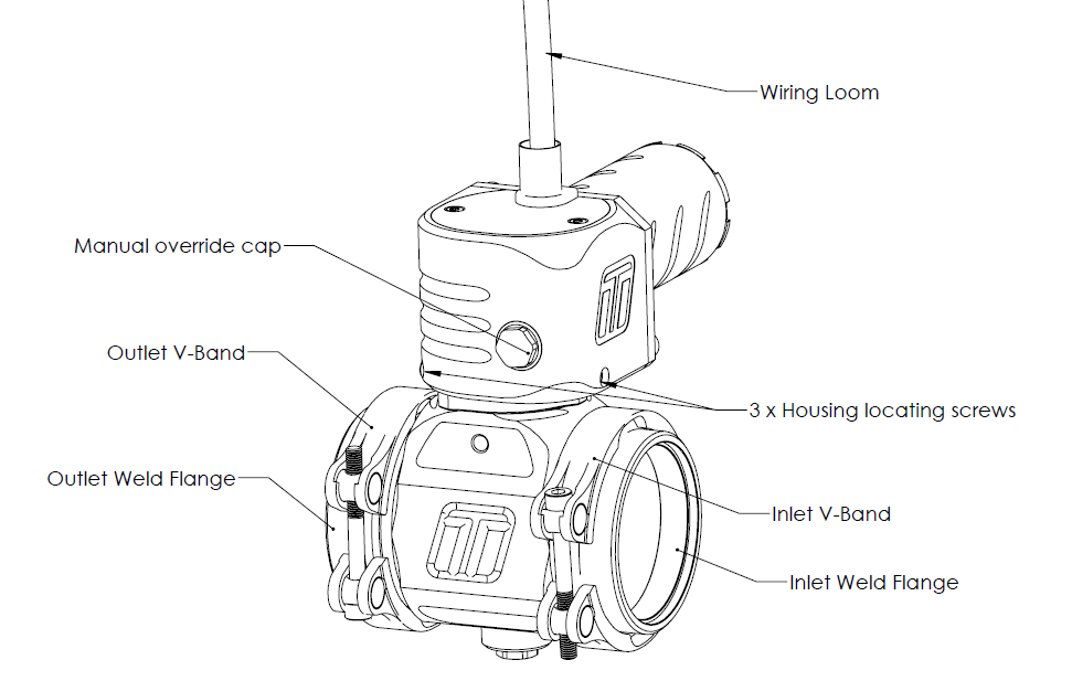
Kit Contents
Part
| Description
| Use
| QTY
|
1
| Turbosmart
Electronic Boost Gate
| Main unit
| 1
|
2
| Inlet
V-Band clamp
| Inlet V-band clamp
| 1
|
3
| Inlet
Weld flange
| Inlet V-band weld flange (O-Ring included)
| 1
|
4
| Outlet
V-Band clamp
| Outlet V-band clamp
| 1
|
5
| Outlet
weld flange
| Outlet V-band weld flange (O-ring included)
| 1
|
6
| Turbosmart Sticker
| Turbosmart sticker
| 1
|
- ¼” drive socket 5mm
- ¼” drive extension
- ¼” drive ratchet
- 14mm square drive deep socket
- Square drive ratchet wrench
- Torque wrench (3/8” drive)
- Metric
Allen Key set - 2.5mm,3mm, 4mm Allen key
- Non-marking spanners to tighten fittings

Suggested Lubricants and Sealants
- Loctite 243 Thread locker
- Loctite 567 Thread Sealant
- Resbond 907TS Red
- Penetrating oil
- Inox MX8 spray grease (Or Equivalent)

CAUTION! It is important
during the setup of the eGate, that some precautions are taken to ensure that
the unit does not malfunction. Firstly, the output from the ECU should be
limited to 15%. As well as an inline fuse (5A-10A) or breaker to protect the
eGate. Once correct operation has been completed, initial safety setups can be
lifted to operational limits.
The Turbosmart Boost Gate is a brand-new way
to control boost pressure, it involves using an electric motor to drive the
position of the butterfly valve, this allows far greater control over
conventional pneumatic boost control during its actuation on the car. This
paired with an aftermarket ECU controlling the boost gate, allows for plenty
of new and safer ways to control boost on your car.
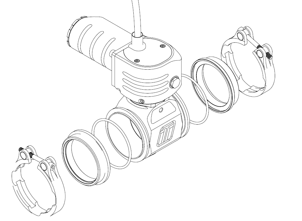
The body will need to be fitted to the vehicle.
This involves the two V
Band clamps. The Inlet (fitted to the intercooler piping), and the outlet which
is where boost pressure is bypasses to (commonly vented to atmosphere via a BoostGate Trumper such at
TS-0265-3001). It is important to have the butterfly
valve manually set to about the middle of its stroke. This will allow for an
easier installation. The Straight Gate can be mounted in either direction.
Please see below for a more detailed and
helpful way of installing the Turbosmart Electronic BoostGate
Turbosmart Electronic BoostGate will
require periodic reapplication of spray grease such as Inox MX8 spray (Any high temperature high pressure grease will
suffice) grease. It is important that the manual override is used to move
the butterfly valve through its range of motion, allowing the grease to be
applied throughout the entire butterfly valve gearbox. Turbosmart recommends
that this is done regularly at least half yearly or more in demanding
temperature environments.
Inspecting motor operation is important to do when using a third party controller incase of issues with the motor. This isn't an issue with the Black Box Controller. Inspection should be done for motor operation after heavy use sessions such as racing weekends
It is also important to check V Band tightness after
the wastegate has run through a couple of heat cycles. To ensure that the BoostGate is seated and sealing correctly.
It is important that the actuator internal housing doesn’t go above a temperature of 150degC (302degF)
as this may cause damage to the internal electronics. Turbosmart recommends
that the BoostGate is installed with good airflow over the body
to help regulate temperature. Turbosmart also recommends data logging the
temperature sensor that is seen inside the actuator.
It is important that the basic tuning
parameters are discussed with a trained professional, please consult your ECU
manufacturer. There are a few basic parameters that are worth noting.
Motor polarity may be important, Depending on how you are driving the BoostGate (external device such as the Turbosmart BlackBox or directly from an ECU) motor polarity may be important to the correct operation of the system. Please check with the manufacturer how they suggest wiring the high power motor drive wires.
Current limitations, it is important that
the allowable motor current is limited a maximum of 20amps for no more than 1 second and 5 amps for more than 5 seconds. It is important that
the current values such as the dead band are correctly set in the ECU to allow
for the motor to only be active if needed.
Sensor Diagnostic limits should be monitored for to ensure correct operation of your BoostGate. The temperature sensor output should not drop below 0.1V or go above 2.15V in normal operations. The position sensor should not go below 0.1V or above 4.9V. Turbosmart also recommends putting in place a tuning strategy that lowers temperatures if the
BosstGate internally exceeds a temperature of 150degC (302degF).
Butterfly Position limits should be set to target
0% for butterfly closed and 90% for completely open. Due to the shape of the butterfly valve on the BoostGate50 maximum flow is actually achieved at 90% open and flow decreases between 90 and 100% opening it us recommended you avoid 100% butterfly opening.
Boost cut should be set to
ensure the safety of your engine a sensible boost cut should be set with in the
ECU to control any possible over boost issues that could be detrimental to
your engine.
The new Turbosmart Electronic BoostGate is Turbosmart’s addition to its
electronic wastegate line-up. A new level of control is now available with the
butterfly valve and offers the option for customers who require another
packaging or new level of control.
Control
With the introduction of the electronic
motor to drive the Electronic Boost Gate, a new level of control is now available to
boost control, there is a wide range of tuning strategies that can be
implemented to better control boost as well as engine protection. This
allows the Engine to maintain much better control over the turbocharger.
Adjustability
The straight gate has multiple options
for orientation of the motor to the body, this is coupled with infinite
possibilities for location of the weld flanges means you really are the master of your own destiny when it comes to the boostgate mounting location. So, if you
need the Electronic Boost Gate mounted in the opposite orientation to stop
fouling with parts within the engine bay, there is an orientation that is
suitable for the Electronic Straight Gate to operate in.
The new boost gate is a world first in its class and features excellent flow properties thanks to our world-leading engineering and
simulation abilities. Thermal performance is a critical key performance factor
within the design of all our products.
Mounting your new Turbosmart
Electronic Boostgate
The weld flanges should be
welded to your intake system. The weld flanges are compatible with aluminium rod material.
The Straight Gate utilises
the pro port weld flanges, this allows for a straight swap over for engines running those blow off valves.
NOTE! The Straight Gate can
be used in both directions. Both directions will regulate the same. It is
advisable however to place the Butterfly Valve pins exhaust side up.
Ideally placing the boostgate on the outside edge of the intercooler will aid in its ability to dissipate as much air as needed to maintain boost control. Two examples are made below. Note that both are possible but the recommendation is for the boost gate to be on the outside perimeter.
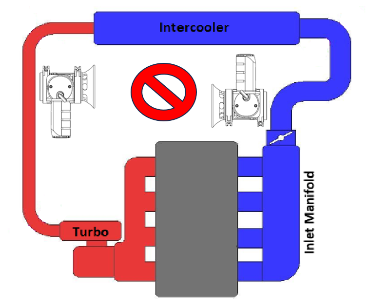
CAUTION! Do not place the Straight Gate
near a significant heat source as this could shorten the life of the internal
electronics.
Fitting your new Turbosmart Electronic BoostGate
Even though possible
to mount the BoostGate gate in both directions, it is suggested that the
Butterfly valve pins are facing away from the intake system.
Prior to mounting the BoostGate, place
v-band over weld on flange by unscrewing the screw on the v-band as
far out as possible and then squeezing the bolt in a syringe motion to expand
the v-band (squeeze the dots together below). Once the v-band is in its fully
expanded position, slide the v-band over the flange to allow for the wastegate
to be installed.
Using a 4mm allen key and a torque wrench tighten
the V-Band to 3N.m (2 ft/lbs). Ensure the boostgate is seated in the v-band flange correctly while
torquing the screw to prevent intake leaks.
It is important that the butterfly valve sits
slightly open for installation. This allows for no interference during the
installation process. This can be adjusted via the manual override.
Connecting your Turbosmart Electronic Boostgate
The Turbosmart Electronic BoostGate wiring has been left unterminated, there are 7 wires.
Wiring Pinout
Revision B (current) – Wiring
| Colour
| Description
|
1 single core
wire each
| Large Gauge
Red
| Motor A
tending towards 0%
|
Large Gauge
Black
| Motor B
tending towards 100%
|
Multi Core
Wire
| Red**
| 5V
|
Black***
| Sensor
ground 0V
|
White
| Position
Signal 0-5V
|
Blue
(Rev B Only)
| *Unfiltered Signal Output
(Position
Output)
|
Yellow (Orange
Rev A)
| Temperature
Signal 0-5V
|
*Note: The Blue
(unfiltered position signal) is not required for use & is for development
purposes only.
**Note: The 5V red wire has no reverse polarity protection, use
only 5V wired in correctly.
**Note: The sensor
ground must be grounded at the ECU Sensor ground and NOT the chassis
Sensor Voltage Limits
| Deg C (Deg F) | Temperature Sensor
Output (mV) |
0 (32) | 2630 |
| 150 (302) | 538 |
Position Sensor
| Target Voltage (V)
| Duty Cycle
|
100% (Open)
| 0.2-0.6V
| ~16%
|
0% (Closed)
| 4.2-4.6V
| -84%
|
CAUTION! Turbosmart recommends calibrating the position sensor using the manual calibration procedure before connecting
the motor wires to your motor drive.
The two large wires are directly connected to
the motor of the wastegate and need to be connected to high power drives in a full bridge configuration like that of an electronic throttle drive circuit,
see your ECU supplier documents for suitable connections. Turbosmart recommends
the eBoostGate should be driven by dual H-Bridge outputs that can supply up to 20A of peak current.
Connect the small red wire to a regulated 5V power
source from your ECU as well as the Black wire to Sensor ground. Connect the
white wire to a 0-5V analogue input on your ecu as well as the orange
temperature sensor signal. The blue wire (Revision B only) is an unfiltered
position output signal for development purposes - This can be left
unterminated.
CAUTION!
- Whilst the temperature
sensor is not required for operation it is recommended for activating failsafe
protocols.
- Ensure all
connections are high quality and away from any heat source.
It is important
during the setup of the eGate, that some precautions are taken to ensure that
the unit does not malfunction. Firstly, the output from the ECU should be
limited to 15%. As well as an inline fuse (5A-10A) or breaker to protect the eGate. Once correct operation
has been verified the fuse and limits can be removed. Calibration
To calibrate the electronic BoostGate
firstly the manual override cap must be removed to allow access to the manual
override. A non marking 14mm is required to remove the cap from the body.
Using a
¼” drive extension with a 5mm socket, turn the manual override in a clockwise
direction with your fingers until the mechanism stops rotating. In this
position the butterfly valve should be seated against the valve seat and will be your 0% position.
CAUTION!
- Do not
apply excessive force to the manual override, doing so will damage the product
and effect the performance.
- Using
your ECU manager software, read the voltage from the sensor and set this as
your closed position.
Wind
the manual adjustment in an anticlockwise direction until it stops. From this
position rotate the adjustment 2 full turns in a clockwise direction. This will place the valve roughly in the 50% position.
Monitor
sensor signal voltage to ensure no wrap around occurs throughout the stroke of
the butterfly valve that could affect operation.
CAUTION!
- It
is critical not to set the 100% position at the end of the travel as this may
lead to seizing of the wastegate and overloading the system.
NOTE! Turbosmart
recommends allowing additional clearance from the end stops until the wastegate
control is tuned to minimise risk of overshoot into end stops at high speeds.
The eBoostGate will come calibrated from
Turbosmart, the targeted values have been set with regards to the position
sensor are approx. 0.5V (completely open) and approx. 4.5V as (completely
closed), It is important to note that as the butterfly valve moves
through its range of motion that the sensor valves are monitored to move
from 4.5V decreasing to 0.5V, 0% open to 100% open. This should be done manually with the ECU
package monitoring voltage values. The electronic motor should be disconnected
at this point.
If the sensor voltage for any reason goes beyond 4.8V a phenomenon known has position wrap around can occur where the sensor output value drop back to zero, this should be avoided at all costs as it will send an incorrect position signal to the ECU.
| Position Sensor | Target Voltage (V) | Duty Cycle |
| 100% (Open) | 0.2-0.6V | ~16% |
| 0% (Closed) | 4.2-4.6V | -84%
|
It
is important to set up the correct limits manually with boost gate. Turbosmart
recommends that the butterfly valve is only ever driven electronically to the
maximum butterfly position of 90%.
Driving
the butterfly valve to 100% will cause increased wear on components such as the
electronic motor as it tries to force the butterfly valve to completely open.
Adjust the calibration to allow plenty of
overshoot to the end stops of the butterfly valve, recalibrate as above once
you have good control of butterfly position.
PLEASE
NOTE that temperatures over 180 degC (356degF) will create an error in the
temperature sensor readings. Therefore, the internal temperature is rated to a
temperature of 150degC (302degF) it is recommended to log and place sufficient
alarms to monitor this.
PLEASE NOTE When driving the electronic actuator, the
current should be limit to no more than 20 amps at a period of 1 second
and 5 amps for more than 5 seconds.
Follow your ECU manufacturers guidelines for
tuning wastegate servo control. Ensure dead band is set to a reasonable level
to not have the output active when not needed.
Sensor Linearisation
Due to the nature of the
butterfly valve design, the flow characteristics are nonlinear. In some cases,
it may be advantages to correlate the linear sensor output to match the flow of
the valve. The following plot compares butterfly valve position with valve
flow. A 3rd order polynomial is provided to relate sensor position
to flow. Note due to the design of the electronic straight wastegate, the
butterfly valve is on a preloaded mechanism to minimise binding at the end
stops, this results in the sensor reading past the home positions and for this
reason the calibration sequence with low
force is essential.
y = -2.1519x3 + 3.0586x2 +
0.0582x + 0.0326
R2 = 0.999
Butterfly Position | Flow Percentage |
0% | 3.3% |
3% | 3.7% |
6% | 4.7% |
10% | 6.7% |
20% | 14.9% |
30% | 26.7% |
40% | 40.8% |
50% | 55.7% |
60% | 70.4% |
70% | 83.4% |
80% | 93.5% |
90% | 99.4% |
100% | 100.0% |
How to Conduct Maintenance On Your Electronic BoostGate
Basic Maintenance
The Straight gate will require periodic
maintenance depending on application. In high demand, unusually environments,
it is advisable to increase the service interval. At a minimum 50 hours is expected.
Turbosmart recommends that the internal gearbox
is regreased with a spray type grease such as Inox MX8 spray grease this should
be conducted half yearly or more depending on environment. With the top plate
removed grease can be sprayed into the small inspection hole located near the
magnet covered by a M4 bolt as well as located near the motor.
Motor Replacement
In the event of the motor failing, it can be easily replaced. The Motor Housing (figure 15) must be dissembled, the cap must be removed with the Turbosmart rear housing tool, this opens the rear of the motor housing. Once open, the motor wires will need to be moved out of the way. The black wire is matched to the red dot on the back of the motor cover. With the wiring clear the 4mm Allen keys will need to be removed. The rear housing will separate. Pulling it off the back. The replacement motor part number (
TS-0550-3123)
A 2.5mm Allen key will be required to remove the motor screws. With both undone. The motor can be lightly pushed out. When reinstalling, use a small application of Loctite 243.
Sensor Replacement
In the event that the sensor fails, it is located under the top cap, it is held on with two 2.5mm Allen keys for the cap and two 2.5mm for the encoder. The replacement sensor part number (
TS-0550-3123). The encoder is located underneath the top cap of the electronic straight gate the grommet will remain attached to the top cap and be removed as one piece.
Actuator Replacement
The actuator can be removed and rotated through 3 different orientations; these are parallel to the body, 30 deg to the body and the current configuration 90 deg to the body.
The actuator locking pins are 3mm Allen keys that lock the body to the actuator. It is important that the butterfly remains in the same position, the recommended position is to be just off the valve seat. It is also advisable to not to move the manual override during this process.
CAUTION! Moving body and actuator while separated will cause issues with calibration. If moving to one of three mounting options observe positions before moving readjusting.
With the Allen key pins removed the body can be separated from the actuator and one of the three options can be picked.
The actuator locking pins are to be Torqued to 6N/mm as well as a new application of Loctite 243 is also required.
Troubleshooting
- Boost gate not actuating - Confirm continuity of wiring, manually adjust butterfly position and feel for binding.
- Poor boost gate actuation – Ensure wiring is correct, check for dirt and smooth operation by manual over-ride, ECU that is driving the butterfly may not be setup correctly.
- Wraparound of signal on position sensor – Turbosmart Pre calibrate every sensor so that this should not occur. Contact Turbosmart if this occurs.
- Boost gate fluctuates and fails to find targeted position, motor wires may be the incorrect way. Swap and test to see. Ensure to use sensible current limits to prevent over currenting.
- Boost gate seized – Remove cap and manually move butterfly feeling for resistance.
- Boost gate moves but sensor not reading – Check connections.
- Boost creeping at high rpm - Boost gate flow path is poor, boost gates too small for the application.
- Failing the above, contact us with information of your engine configuration and photos of installation.