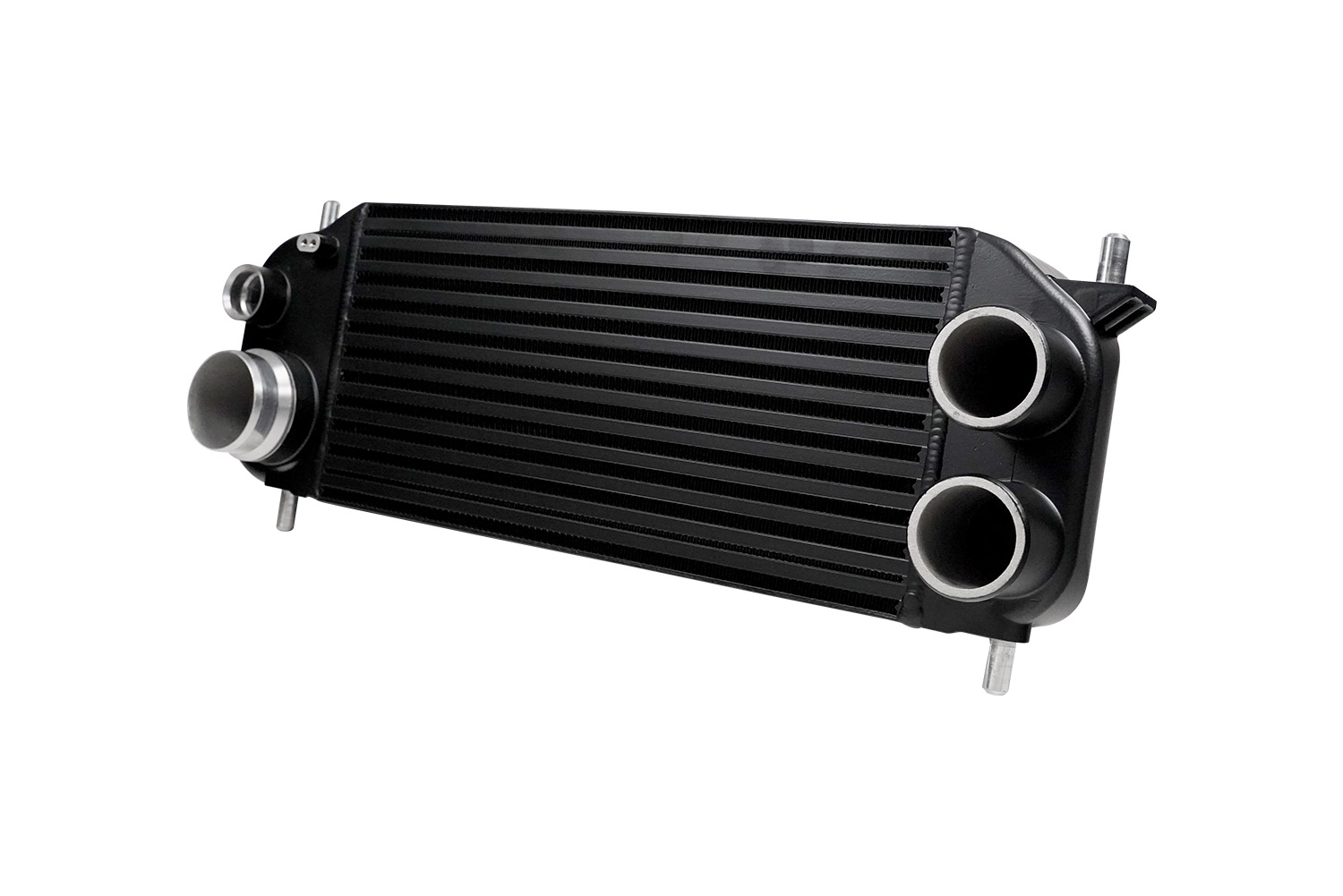
TS-CCA-VSFD001S/B - Performance Intercooler Upgrade Suit Ford F150 EcoBoost
Product Name: | Performance Intercooler Upgrade suit Ford F150 EcoBoost |
Product Description: | Air to Air Intercooler |
Product Number: | TS-CCA-VSFD001S/VSFD001B |
Important notes on your new Intercooler
- Turbosmart accepts no responsibility whatsoever for incorrect installation of this product which is potentially hazardous and can cause serious engine damage or personal injury.
- Turbosmart intercoolers is designed for use as a factory replacement for a turbocharged vehicles OEM intercooler.
- Ensure the engine is cold prior to installation.
Recommendations
- Turbosmart recommends that your intercooler is fitted by an appropriately qualified technician.
Kit Contents
|
Part |
Description |
Use |
|
1 |
Turbosmart Intercooler |
Main unit |
|
2 |
Instruction Card |
Instruction Card |
|
3 |
Turbosmart Sticker |
Turbosmart sticker |
Tools Required
Allen key set metric
Screwdriver
Basic socket set
Torx bits
Fitting your Intercooler
Identify intercooler location
On the 13th Generation Ford F Series Truck (P552)
the intercooler is located at the front of the vehicle located on the lower portion of the car behind the number plate. It is easily accessible from the bottom of the car.
Removing the Undertray
Remove the under-tray of the vehicle by removing all
the plastic clips holding the tray in place. Once the under-tray is removed,
the intercooler assembly can be accessed.
NOTE!
It may be required to remove auxiliary components to access the diverter valve, ensure you consult your local specialist or a service manual for correct disassembly procedures.
Remove Intercooler Piping
The Turbo feed charge pipe also need to be
removed. These are also held on with 7mm hose clamps.
Remove Diverter Valve Plug
Remove
Diverter Valve Chamber
The chamber is held on at the top of the intercooler with 1 x 8mm self-taping screw. Once removed the chamber is free to be removed.
The chamber pictured below can be removed, the chamber is simply rotated anticlockwise and it will uncouple from the intercooler.
Mounting
Turbosmart Diverter Valve
The
alignment of the diverter valve is important. The diverter valve can screw in with two directions.
The recirculation port must face towards the intercooler as pictured above.
The
mount that holds the valve comes in two options. The most suitable one needs to
be used. The Smaller right angled one pictured is for the small version
intercooler. We must use a M3 Allen key to attach to the diverter valve.
Refitting Diverter Valve/Intercooler to Car
With everything fitted back to the
intercooler we can fit the intercooler back into the car. It’s helpful to use
the intercooler bracket to assist with the intercooler to remain in place.
The turbo feed pipes as well as charge
pipe to the throttle body must be refitted, the charge pipe needs an audible
click to sound from the retention clip.
The two 7mm hose clamps must be correctly clamped.
The recirculation pipe must be fitted
ensuring the connector clips and locks into place, at this point we should
tighten up any loose hose clamp to ensure that we have correct orientation of
the recirculation pipe
Refitting Electrical Connector
Plug in Connector ensuring that a positive and audible click is heard with the connector to ensure that it is locked in place.
Refit Undertray with the 2 x 15mm bolts that were moved to originally gain access to the Diverter valve area.
It is important to check for leaks and correct operation, ensuring no leaks are present and all hoses are correctly seated.
- Diverter valve not actuating - Confirm electrical signal plug is connected appropriately, as the plugs are new, some force may be required to click the plug into place.
- Valve is staying open - Confirm the valve has O-rings as they may have been dropped or lost during installation.
- Boost Pressure loss or lower than before - Confirm the valve has O-Rings as they may have been dropped or lost during installation. Intercooler Pipes are correctly seated.
- Failing the above, submit a technical request to tech@turbosmart.com.au with information of your engine configuration and photos of installation.
- As the factory engine control unit controls the valve, the diverter valve is almost silent.
NOTES ON EM SERIES DIVERTER VALVE OPERATION
- Due to its construction, your EM series may be much more audible than the OEM valve
- During normal operation you may now be able to hear the valve open for a few seconds under the following events: traction control, cruise control management, rapid gear changes and varying throttle position changes. This is standard operation of your diverter valve and is coded as part of the torque management software in the OEM engine control unit; there is no adjustment available over these functions on the Turbosmart EM valve directly. It is normal for a diverter valve to be “very active” as it protects your turbocharger from surge events as well as bypassing air for torque management purposes.
Related Articles
TS-0225-1202 - F150 EM Series Diverter Valve
Product Name: F150 EM Series Diverter Valve Product Description: EM Series Diverter Valve F150 Product Number: TS-0225-1202 Important Notes On Your New Diverter Valve Turbosmart accepts no responsibility whatsoever for incorrect installation of this ...TS-0203-1018 - BOV Kompact Hyundai Genesis
Product Name: Hyundai Genesis 2.0T Product Description: BOV Kompact Supersonic - Honda Civic 1.5L Product Number: TS-0203-1018 Important Notes On Your New Diverter Valve Turbosmart accepts no responsibility whatsoever for incorrect installation of ...TS-0223-1X88 - BOV Kompact EM Dual Port VR5 - Instructions
Product Name: BOV Kompact EM Dual Port VR5 Product Description: BOV Kompact EM Dual Port VR5 Product Number: TS-0223-1X88 Document Version: V1.00 Rev A Important Notes on Your BOV Turbosmart accepts no responsibility whatsoever for incorrect ...TS-0223-1082 - BOV Kompact EM Series - Instructions
Product Name: BOV Kompact EM Series Product Description: BOV Kompact EM Series Product Number: TS-0223-1082 Document Version: V1.00 Rev A Important Notes on Your BOV Turbosmart accepts no responsibility whatsoever for incorrect installation of this ...TS-0223-1266 - EM Series Diverter Valve VR2
Product Name: Kompact EM VR2 Plumb Back Product Description: Kompact EM VR2 Plumb Back Product Number: TS-0223-1266 Important notes on your new Diverter Valve Turbosmart accepts no responsibility whatsoever for incorrect installation of this product ...