Pneumatic Boost Gate Compressed Gas
Product Name: | Pneumatic Boost Gate Compressed Gas |
Product Description: | PBG 50/76 Pneumatic Boost Gate Compressed Gas 7 Psi /Solenoid |
Product Number: | TS-0265-1242 TS-0265-1252 TS-0267-1242 TS-0267-1252 |
 Important Notes on Your New Compressed Gas Boost Gate
- Turbosmart
accepts no responsibility whatsoever
for incorrect installation of this product which is potentially
hazardous and can cause serious engine damage or personal
injury
- The compressed gas boost gate is designed for use with a forced induction engine. The boost gate bypasses some of the intake air flow(boost pressure)in order to control total boost delivered to the engine.
- Consult your local specialist before setting
your desired boost pressure,
setting boost beyond your
engines capability may result in engine damage.
- Use only high-quality fittings ensuring maximum sealing reliability. Optional Turbosmart fitting kit available.
 Recommendations
- Allow for
adequate cool airflow around the top diaphragm housing
- DO NOT Mount the boost gate so that the top diaphragm housing is less
than 100mm from a heat source
- Fitting
your compressed gas boost gate may require fabrication or modification to your intake piping. Turbosmart recommends that your boost gate is fitted by an appropriately qualified technician.
- Turbosmart
recommends that the engines Air/Fuel ratio is checked while setting the desired
boost pressure, as any increase in boost pressure can cause the engine to run “LEAN”, resulting in possible
engine damage.
- Turbosmart
recommends that boost pressure is set using
a dynamometer and not on public roads.
- Turbosmart recommends that a boost gauge be permanently fitted to the vehicle.
 Kit Contents
Part | Description | Use |
1 | Turbosmart Compressed Gas Boost Gate | Main Unit |
2 | Inlet Weld Flange | Inlet Weld Flange |
3 | Outlet Weld Flange | Outlet Weld Flange |
4 | Inlet V-Band Clamp | Inlet V-Band Clamp |
5 | Outlet V-Band Clamp | Outlet V-Band Clamp |
6 | Collar Tool | Collar Tool |
7 | Spring Kit | 4 x Springs ** (1x Spring pre installled)** |
8 | Turbosmart Sticker | Turbosmart Sticker |
Tools Required
- 3/8" square drive deep socket
- Square drive ratchet wrench
- Torque wrench (3/8" drive)
- Non-marking spanners to tighten fittings
- 3/16" hex key
- Supplied collar tool
- 14mm 12-point (double hex) socket
- Flat blade screwdriver
SUGGESTED
LUBRICANTS AND SEALANTS
SUGGESTED
LUBRICANTS AND SEALANTS - Loctite 243 Thread locker
- Loctite 567 Thread Sealant
- Resbond 907TS Red
- Penetrating oil
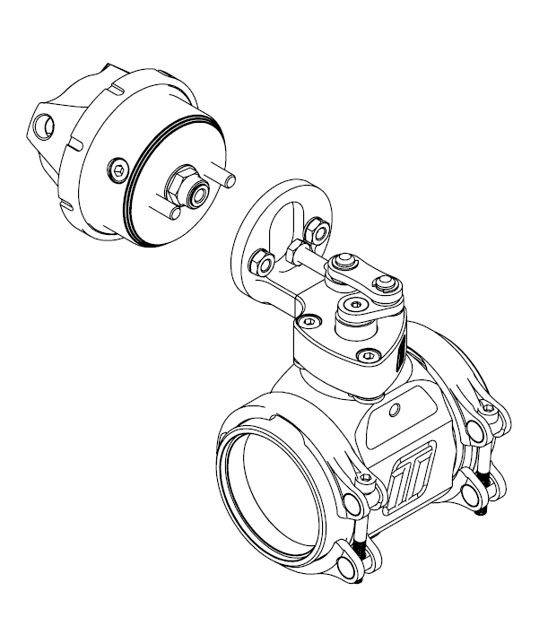
Compressed Gas Boostgate Overview (Pictured without Solenoids)
Fitting Your CO2 Boost Gate
Mounting your new Turbosmart Pneumatic CO2 Boostgate
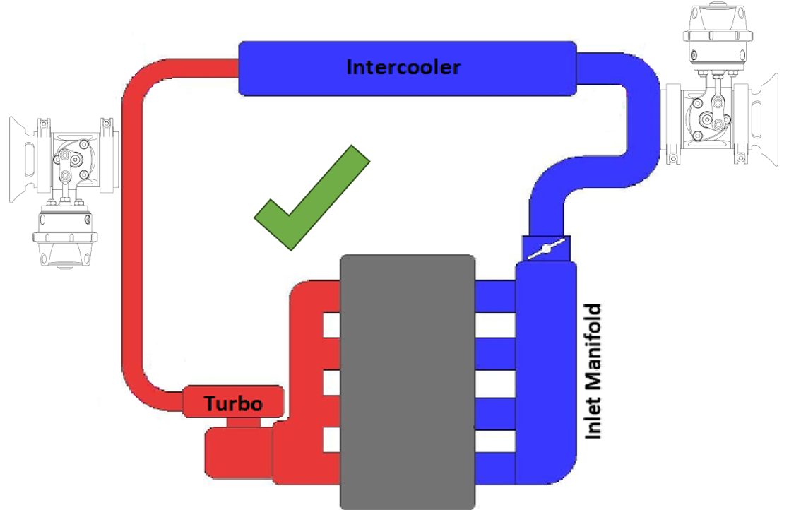
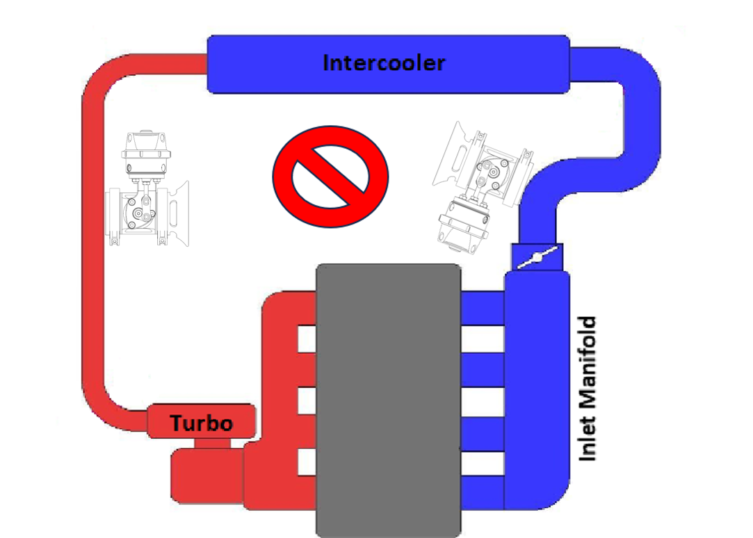
 Do not place the actuator cap near a significant heat source as this could shorten the life of the diaphragm.
Fitting the Compressed Gas Boost Gate
Prior to mounting the Boost Gate, place v-band over weld on flange by unscrewing the nut on the v-band as far out as possible and then squeezing the bolt in a syringe motion to expand the v-band (squeeze the dots together below). Once the v-band is in its fully expanded position, slide the v-band over the flange to allow for the boost gate to be installed.
Fit Actuator Port Fittings

Clocking Actuator
Compressed Gas Boostgate Hook-Up
Compressed Gas Setup
- Port 1 (Regulated CO2 Supply)
- Port 2 (CO2 "Top Cap")
- Port 3 (Blocked)
- Port 1 (CO2 "Top Cap")
- Port 2 (Vent to Atmosphere)
- Port 3 (Blocked)
(Optional) Integrated Solenoid Gas Setup
- Port A (Regulated CO2 Supply)
- Solenoid A
- Port B (Vent to Atmosphere)
- Solenoid B
Wiring Hookup
Start Engine and check for leaks.
Congratulations,
your CO2 Boost Gate is installed and ready for use. Double check all fittings,
lines and mountings then proceed to start engine and check for leaks.
HOW TO CHANGE YOUR COMPRESSED GAS SPRING
Remove Compressed Gas Boost Gate from Manifold
Remove Top Cap
Familiarise
Yourself with Cap and Body Notches
Locate cap and body notches and grooves which dictate the alignment of the cap. These notches are used to locate the cap onto the body and must be aligned prior to compression of the cap onto the body.
Press Cap
onto Body
Using a press or vice, comp the notches are remaining aligned. Once the cap has seated home onto the body, screw the collar down by hand in a clockwise direction. While still in the press or vice, Tighten the collar further with the collar tool until the collar will not turn.
Reinstall
Compressed Gas Boost Gate
Achieving Your Target Boost Pressure
There are various factors involved in achieving your target boost pressure including.
- The size of
the spring fitted in your boostgate i.e. the boost pressure achieved by the
boostgate spring only.
- The desired level of boost pressure and the difference between this and your boostgate spring pressure.
- The size of
your turbocharger and boostgate and the resulting exhaust manifold back pressure in your system.
- The amount of dome pressure that is fed into the top cap.
IMPORTANT
NOTES ON SETTING THE BOOST GATE SPRING
PRESSURE Location | Inner | Inner | Middle | Outer |
Pressure | 6psi | 9psi | 12psi | 21psi |
Colour | Black | Grey | Pink | Red |
6psi | ● |
|
|
|
9psi |
| ● |
|
|
12psi |
|
| ● |
|
18psi | ● |
| ● |
|
21psi |
| ● |
How to Change Your Boost Gate Diaphragm
Remove Actuator from Body
Remove
fittings from the boost gate as well as the
breather hose if fitted. Unscrew outlet V-Band nut in a anti-clockwise
direction to the very end of the thread, Squeeze the nut
against the V-Band in a syringe like motion to expand the V-band over
the flange. Repeat for inlet V-Band. Remove boost gate. Mark the orientation
of the valve to the body with tape or a paint pen.
Diaphragm Replacement
The actuator must be removed for ease of disassembly of the diaphragm replacement. The once removed the top cap can come off and the diaphragm can be swapped out.
Align the
valve orientation marks and confirm the diaphragm bead is
seated in the groove of the actuator. Install desired spring combination. Configure
Boost Gate with preferred spring combination of inner,
middle and outer springs
Familiarise
Yourself with Cap and Body Notches
Locate cap
and body notches and grooves which dictate the alignment
of the cap. These notches are
used to locate the cap onto the
body and must be aligned prior to compression of the cap onto
the body.
Press cap
onto body
Using a
press or vice, compress the cap onto the body ensuring the notches
are remaining aligned. Once the cap has seated home onto
the bod, screw the collar down by hand in a clockwise direction.
While still in the press or vice, Tighten the collar further with the
collar tool until the collar will not turn.
Reinstall fittings to the cap of the boost gate using fresh sealant.
Reinstall boost gate
HOW TO INSTALL A SENSOR CAP TO YOUR COMPRESSED GAS STRAIGHTGATE
The Compressed Gas Boost Gate comes with a pre-installed magnet on the diaphragm, essential for HE sensor operation. To install the sensor (sold separately), simply remove the top blanking plate and fit the HE sensor in its place. Calibration may be required depending on your system.
Connect the wires to your data logger accordingly. Use a high-quality connection to reduce noise and calibration fluctuation.
To ensure longevity from the sensor, ensure adequate airflow is supplied directly to the sensor to avoid overheating or sensor failure.
Turbosmart HE sensor has an operation temperature window of -40C up to 170ºC (340ºF) junction temperature, for temperatures outside of this window the VOUT will revert to less than 2.5V
Temperature
exposure above 260ºC (500ºF) can cause permanent damage to the sensor.
Calibration*
Insert the
relevant calibration curve into your data logger for the Compressed Gas Boost Gate
Rod Travel (mm) | Voltage Out |
0 | 0.44 |
2 | 1.21 |
4 | 1.58 |
6 | 1.84 |
8 | 2.00 |
10 | 2.13 |
12 | 2.21 |
14 | 2.27 |
16 | 2.32 |
18 | 2.36 |
*NOTE! For best
results, each boost gate should be calibrated to your
setup. Troubleshooting
- Boost Gate not actuating - Confirm signal hose is plumbed to a pressure only source,
confirm preload on valve seat during installation
- Poor
boost gate actuation - Ensure signal hose is not shared and is sourced as close
to the compressor as possible, check seal on fittings
- Poor
boost gate actuation - Confirm Top ports are not blocked and free from debris
- Boost
creeping at high rpm - boost gateflow path is poor, boost gate is too small for
the application
- Failing the above, submit a Technical Request Form with information about your engine, oil type and photos of the installation and one our expert technicians will respond as soon as possible.
Related Articles
Compressed Gas / CO2 External Straight Gate Instructions
Product Name: Compressed Gas Wastegate Product Description: PSG 40/50/76 Pneumatic Straight Gate Compressed Gas 7 Psi Product Number: TS-0565-1242 TS-0565-1252 TS-0563-1242 TS-0563-1252 TS-0567-1242 TS-0567-1252 Important Notes on Your New Compressed ...Gas Valve Actuator
Product Name: Gas Valve Actuator Product Description: GVA 40/45/50/60mm Product Number: TS-0552-1712 TS-0553-1712 TS-0554-1712 TS-0555-1712 Important notes on your new Gas Valve Actuator (GVA) Turbosmart accepts no responsibility whatsoever for ...TS-0265-1042 - eBG50 Electronic Boost Gate
Product Name: eBG50 Electronic BoostGate50 Black Product Description: eBG50 Electronic BoostGate50 Black Product Number: TS-0265-1042 Important notes on your new Electronic Boost Gate The electronic boost gate is designed for use with a forced ...Pneumatic Boost Gate
Product Name: Pneumatic Boost Gate Product Description: PBG 50/76 Pneumatic Boost Gate 7 Psi Product Number: TS-0265-1762 TS-0267-1762 Important Notes on Your New Boost Gate Turbosmart accepts no responsibility whatsoever for incorrect installation ...Compressed Gas / CO2 External Wastegate Instructions
Product Name: Compressed Gas Wastegate Product Description: GenV Compressed Gas Wastegate Product Number: TS-0552-1242 TS-0553-1242 TS-0554-1242 TS-0555-1242 Important Notes on Your New Compressed Gas External Wastegate Turbosmart accepts no ...